
During product development, modifying complex 3D models can be challenging when the workflow relies entirely on traditional feature-based modeling history. Synchronous Modeling in Designcenter NX offers a more flexible approach, allowing engineers to directly edit and optimize model geometry quickly and efficiently.
Whether working with native design data or files imported from other CAD systems, this toolset provides flexible editing capabilities that can significantly improve productivity, even when working with large assemblies.
1. Move Face – Flexible Geometry Modification
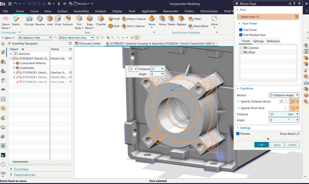
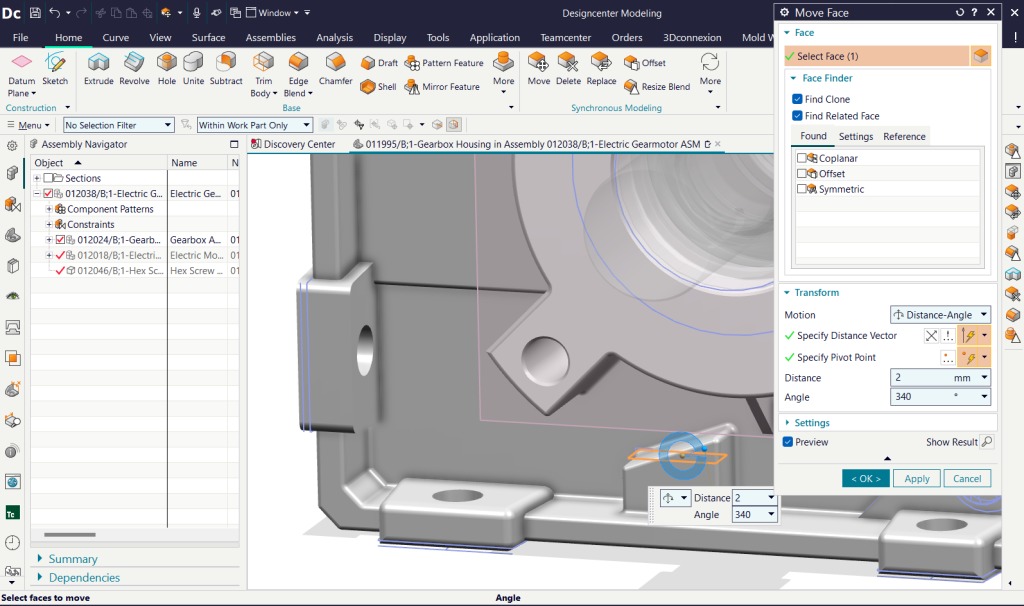
One of the core capabilities of Synchronous Modeling is the ability to manipulate model faces directly. A key tool is the Move Face command.
Instead of searching through the feature history and modifying individual parameters, engineers can select one or more faces and move them directly.
- Intuitive interaction: Drag the on-screen directional handles to quickly adjust distances or rotation angles.
- Precise input: Enter the required distance or angle directly into the command dialog for accurate control.
2. Resize Hole – Quickly and Consistently Modify Holes
When working with mechanical components containing threaded holes or bolt holes, maintaining consistent dimensions is essential. The Resize Hole command in Synchronous Modeling helps engineers make these modifications efficiently.
After selecting a hole face, the command interface displays the Face Finder tab, which includes the Find Clone selection filter. This intelligent feature automatically identifies and selects holes with matching geometric characteristics throughout the model.
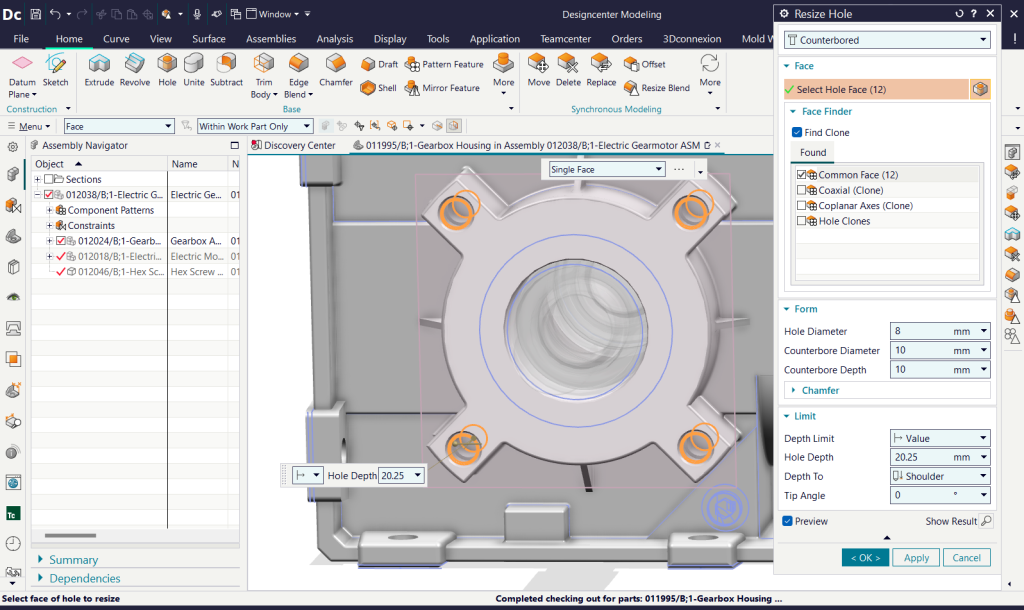
Rather than modifying each hole individually, engineers can apply changes to all matching holes in a single operation, ensuring dimensional consistency while saving considerable time.
3. Replace Face – Maintain Consistent Geometry
In many cases, design data received from partners or imported from other CAD systems contains no feature history. This can make it difficult to establish symmetry or achieve the required fit between components.
The Replace Face command allows users to replace an existing face with a reference face. This helps restructure the model and achieve the required symmetry and original design intent without rebuilding the entire model from scratch.
4. Delete Face – Remove Unnecessary Geometry and Clean Up Models
Effective design improvement sometimes comes from removing unnecessary details. The Delete Face command allows users to delete selected faces directly, creating simpler, cleaner geometry without suppressing features or modifying a complex feature tree.
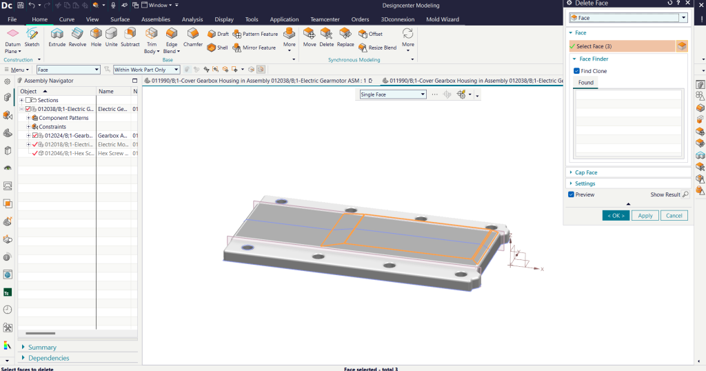
This approach is widely used to:
- Clean up models imported from other CAD software
- Remove features that are no longer required
- Simplify geometry for subsequent machining operations
5. Resize Pattern – Flexibly Modify Repeating Patterns
Repeated features, such as bolt-hole arrays and cooling fins, can take considerable time to redesign from scratch. The Resize Pattern command provides an intuitive way to modify both the number of instances and their spacing.
The process is straightforward:
- Step 1: Select any face belonging to an existing pattern. The system automatically identifies the associated pattern geometry.
- Step 2: Change the number of instances or adjust the spacing between them.
- Step 3: Use Show Results to preview the changes.
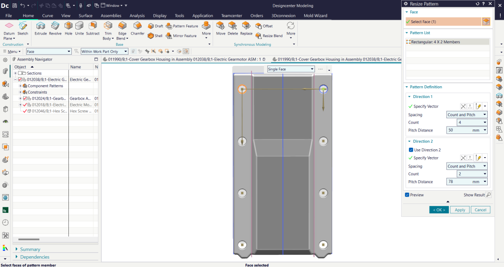
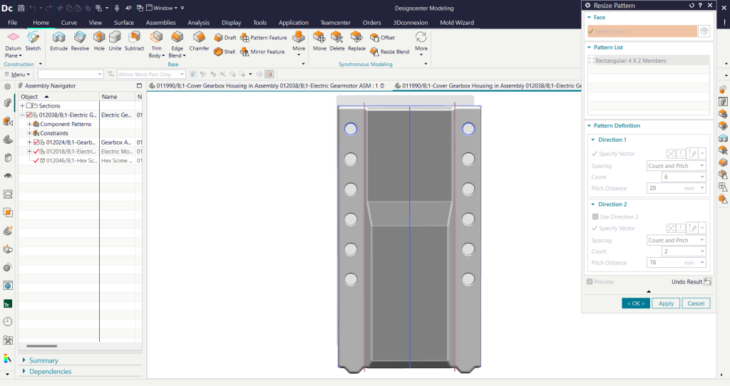
This enables engineers to update existing patterns quickly and accurately without recreating them from scratch.
6. Radiate Face – Offset Geometry Along a Radial Direction
For rotational components such as gears, the Radiate Face command provides a specialized offset method rather than moving a face along its conventional surface normal.
-
How it works: The command offsets geometry in a direction perpendicular to the rotational axis, helping preserve the accuracy of cylindrical surfaces and axisymmetric components.
-
Applications: Calculating material shrinkage in mold manufacturing, defining precise machining allowances, and designing interference-fit joints.
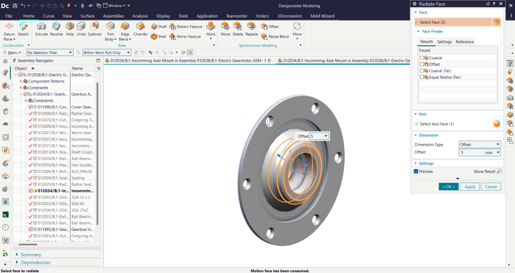
Users simply select the cylindrical face and enter the offset value. Siemens NX then automatically handles the underlying geometric operations.
Read more:
- Designcenter 2606: Discover the Latest Features
- Designcenter X Solid Edge: Flexible Design and Seamless Collaboration Anywhere
- Designcenter 2606 Mold Wizard: Improve Mold Design with the Latest Updates
Conclusion
The Synchronous Modeling toolset provides a flexible alternative to traditional feature-based modeling. By editing actual model geometry directly, engineers can optimize, modify, and manage complex models and assemblies more efficiently, regardless of the original source of the design data.
For businesses working with imported CAD files or complex 3D models, these capabilities can simplify design changes, reduce manual work, and improve engineering productivity.
Contact Vietbay for a consultation on genuine Siemens NX software solutions.