National Instruments leverages Valor NPI for DFM to enhance new product introduc-tion and production efficiency
Business challenges
- Reduce the time it takes to run a complete DFM analysis
- Reduce disruption to product design
- Enhance new product intro-duction and production efficiency
- Increase team members’ confi-dence in promised results
Keys to success
- Leverage close working relationship with Siemens Digital Industries Software
- Integrate Valor NPI in phases instead of trying to implement it all at once
- Implement methodical rollout, monitoring and revising procedures for best results
How did NI apply DFM to its process?
NI (formerly National Instruments) has taken a journey from using all manual pro-cesses to instituting some design-for-manufacturing (DFM) to embracing the benefits of DFM and plan-ning for full adoption. Their initial use focused on using Valor™ NPI software for final DFM checks before release to manu-facturing. They began implementing a more upstream DFM flow, first for focusing on part validation earlier and then inte-grating concurrent DFM during design. Previous methods for part validation and final DFM required an average of four to five days per new product. After moving to the new flow, they have reduced the average DFM cycle time by 60 percent to just one-and-one-half days and are adding additional coverage and anticipate it will eventually be closer to one day.
Initial DFM implementation
NI’s first implementation was quite similar to a number of companies’ entry into DFM software, as shown in figure 1. Like many implementations, the initial use was to execute a DFM check before releasing the design to manufacturing and correcting any manufacturing issues before release. To more efficiently use resources, they chose to make a single engineering rule file (ERF) that would apply to all printed circuit boards (PCBs). The rules were written and managed by the DFM engineers.
The result was also similar to what a number of companies have discovered. First, there was a tremendous benefit resulting from finding manufacturing issues prior to release to the fabricator and being able to correct them. That saved additional itera- tions with the fabricator, which was previously the case with the fabricator running DFM. However, as illustrated in figure 2, the in-house DFM check can be used to discover potential issues from all phases of PCB development prior to releasing to fabrication.

Figure 1. Initially, a DFM expert was to run a final check before release to fabrication.

Figure 2. Running DFM at the end resulted in necessary corrections from a number of sources.
Typical errors that were discovered included part selection and creation, invalid space for components, copper and net, various mechanical and manufacturing rule nonconformities and electrical updates. Although these can be discovered in-house, the re-spins of the board required a similar engineering effort in response to issues resulting from the fabricator doing the DFM check.
Creating a new DFM flow
Although there were significant benefits to performing DFM checks before releasing it to the fabricator, errors still had to be rectified, sometimes requiring a significant amount of effort and time, especially if the error was early in the design cycle. Working with Valor, which is part of the Siemens Xcelerator business platform of software, hardware and services, in 2014 NI made the decision to move the DFM upstream as far as possible, or in Valor vernacular, to “shift left.” The goal of the new DFM flow was to move DFM checks to each stage of design so manufacturing issues could be detected and corrected at that stage instead of waiting to find the error at the end of the design. The expected result was that both time and cost would be saved by fixing problems as they occurred. Figure 3 shows the cpmplete new flow, which was executed in phases.
The first step in creating the new flow was to define DFM within the context of NI’s business needs. The resultant DFM guidelines are shown in table 1. One of the primary goals was to use their current processes and capabilities to minimize the learning curve and disruption of their existing design flow. In addition to defining the guidelines and rules, they created a set of objectives for the upstream project. Figure 4 is a representation of their four primary objectives.
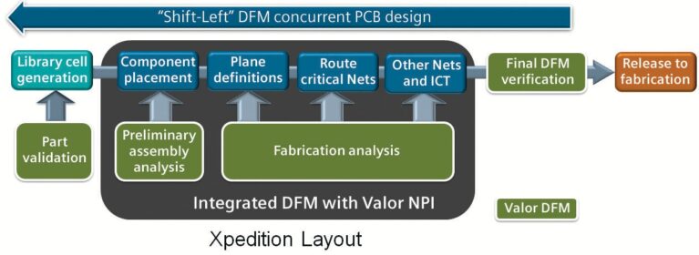
Figure 3. The new DFM flow includes executing concurrent DFM during design so issues that can affect fabrication or manufacturing will be uncovered and rectified before the design moves forward.
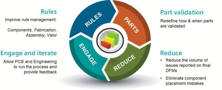
Figure 4. The four objectives of the upstream project.
Part validation with DFM was executed with Valor NPI and the Valor Parts Library (VPL)
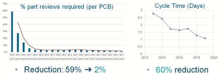
“The bottom line: part reviews went from requiring 59 percent to 2 percent of the total number of components on the board, and the corresponding savings in time facilitated a 60 percent reduction in DFM cycle time as well as realizing a primary objective of reducing the number of DFM issues,” says Chris Smith, senior engineering services group manager.
Read more:
Contact us for free and detailed advice:


