Solid Edge Model Based Definition (MBD) allows engineers to create complete technical definitions and annotations of parts or 3D assembly models, making models easier to understand and more intuitive than complex drawings complexity, thereby reducing time spent on technical documentation, promoting rapid production and product validation.
In this article, Vietbay will mention improvements to Model-Based Definition (MBD) in Solid Edge 2024.
The new MBD and Product Manufacturing Information (PMI) features get us closer to going completely paperless. We spend up to 15% of our time printing and organizing drawings, and Solid Edge 2024 could help us eliminate that completely – Daniel Schulz, KAESER
MBD Creation
With new Model Based Definition capabilities in Solid Edge, lower the 3D communication barrier and better convey design intent for downstream manufacturing processes.
You can intelligently define and annotate 3D models with automated assistance and improved capabilities in Solid Edge Model Based Definition to deliver consistent model dimensioning and annotations while reducing ambiguity.
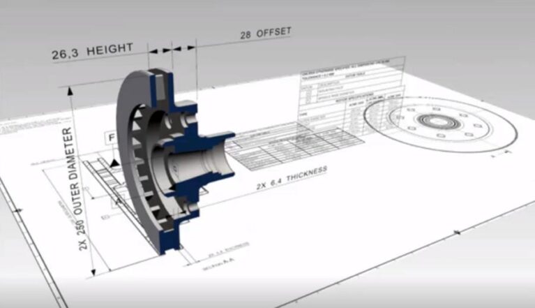
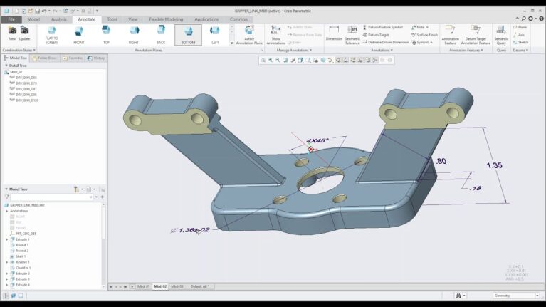
Improved “Auto Dimension” tool
Enhanced and customizable location and size dimension placement results in clean, easy-to-read model dimensions. Users can automatically dimension location and size callouts for created slot and oval cutouts, saving time and energy by instantaneously counting the total of radial, fillet and chamfer dimensions in the model with the “Total Count” command. Improved support enables users to define one or two datums for automatic dimensioning of turn parts.
“Arrange Dimensions” command now supports coordinate dimensions
Locate coordinate dimensions as a regular part of workflows alongside other dimension types in both the 3D and draft environments. Coordinate dimensions are automatically arranged first with other dimensions arranged around them, resulting in improved model views.
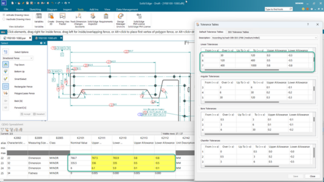
New “Dimension Checker” command
Quickly and easily identify the constraint status of features and parts with the new “Dimension Checker” command for improved speed of creation. The model is automatically color-coded to indicate the constraint status, and feature IDs are immediately populated and cross highlighted from the dialog for instant identification of various constraint statuses, including dimensions with no tolerances.
Angular Jogs on Coordinate Dimensions (Draft and PMI)
The Dimension Style/Dimension Properties dialog now includes an option to ‘Enable angular jogs’ to instantly display jog lines as parallel, improving readability and organization on designs.
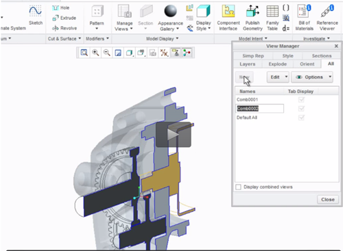
Model views of standard view orientations
Save time and energy by automatically creating common model views with the new “Common Model Views” command. Utilize the “Common Model Views” command alongside “Auto Dimension” to accelerate creation of standard view orientations. Previously created common model views intelligently display the PMI information relevant to the selected model view, allowing users to switch between views quickly and easily.
Update of model views
The new “Update Model Views” command automatically updates all model views when the model changes or PMI is added or removed, reducing the need to manually update each model view.
Improved Model View Vertical Command Bars
Improved Model View Vertical Command Bars simplify the model view process and eliminate hidden options in the dialogue, reducing the number of mouse clicks and errors. Users can easily apply desired section views to model views with sections highlighted graphically, eliminating the need to navigate to the Pathfinder. Include the recently created
model view by default in 3D Publish PDF with the new option in the Model View Vertical Command Bar to ensure automatic creation and save time.
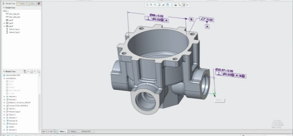
Auxiliary Plane Indicators for Feature Control Frames
New “Auxiliary Plane Indicators for Feature Control Frames” capability allows users to create auxiliary plane indicators displayed next to the tolerance indicator to provide improved ISO standard support.
Weld symbol enhancements
Compound weld symbols can now have Root Openings and Groove Angles placed inside the symbol, automatically shifting the other weld specifications mentioned and simplifying the workflow
MBD Publish
With improved MBD publishing tools, intelligently deliver design information through easily customized templates and better convey design intent for downstream manufacturing processes.
Section views
To streamline the delivery of relevant design information, users can now export PMI views with sections to 3D PDF, including those created with single planes in the “Section by Plane” command.
PMI face association in 3D PDF
Boost part inspection and manufacturing processes with new PMI face association, highlighting parent faces and section views automatically when they are selected in the 3D PDF.
Parts list customization
Have full control over the customization of column sizes, fonts, and styles with the “Parts List” command in the template editor environment. Define standard and custom properties from the assembly as columns with options to add exploded and atomic Parts Lists. Parity with the “Parts List command” in Solid Edge 2D drafting enables users to utilize everything from the 2D drafting environment in the template editor environment.
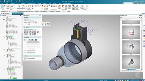
3D PDF display quality
Select from various render modes to export to the 3D PDF for newly created model views, enabling quality customization to better fit customer needs.
Source: Siemens
Contact us: