Achieve first-pass success in electromechanical design using industry-proven tools that simulate and verify electrical behavior as a design is created. Solid Edge Wiring Design provides rapid and intuitive electrical circuit design with built-in verification and design rule checks to validate designs.
Solid Edge Wiring Design provides rapid and intuitive electrical circuit design using industry-proven tools that simulate and verify electrical behavior as the design is created. The graphical design environment creates wiring schematics via an intuitive user interface and built-in libraries of electrical symbols, components, and simulation models. More than 10,000 popular industrial parts support the automated selection of parts, terminal plugs and seals for each connector.
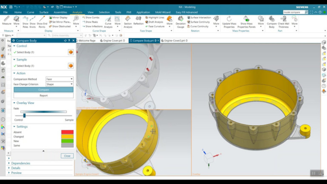
Simulation highlights design challenges such as short and open circuits, voltage drop, fusing, and wire sizing errors as a design proceeds.
Solid Edge Wiring Design automates standards-based diagram generation and cross-referencing for multi-sheet schematics, and automatically generate reports for wires, connectors, and devices used in a design.
Capabilities
Streamline design process
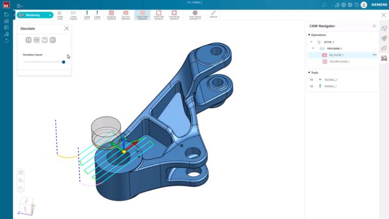
Solid Edge Wiring Design is an electromechanical solution that enables data to flow seamlessly between the 2D schematic capture application and 3D MCAD domains, allowing teams to understand and trace the impact of design decisions across domains.
ECAD/MCAD collaboration
Advanced design automation
Virtual prototyping
Electromechanical design as it’s meant to be, enabling fully functional and manufacturable electromechanical designs created in a seamless ECAD/MCAD environment. Design electrical systems while simultaneously collaborating with mechanical design to optimize product design.
Built-in intelligence automates many design tasks, updating diagram, device and wire index tables as changes are made. Streamlined graphical rendering and manipulation produce high-quality diagrams and allow easier object location and interaction. Autoroute capabilities automate routing for a full signal path, including junctions.
Ensures circuits perform to meet customer requirements using strong simulation capabilities that enable virtual prototyping of electrical circuits. Full electromechanical digital mockups remove the need for costly prototypes and enable rapid evaluation of changes.
Product design optimization
Cabinet panel layout
Data-compatible integrations
Facilitate the accommodation of space reservation, clash detection and hazard avoidance in the mechanical domain. Potential problems, such as short circuits, are highlighted.
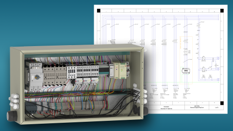
Accurate physical layout and schematic drawings for successful cabinet panel design. Includes a configurable and reusable layout design capability, which can be used in the preparation of 2D industrial control panels.
Full data compatibility for customers using Siemens Capital and/or Teamcenter applications. Transfer 3D designs and bill of materials (BOM) from wiring design to PLM or use data derived from Solid Edge Wiring Design in Capital enterprise solutions.
Free Trial
Solid Edge Wiring Design and Harness Design Try our professional wiring and harness design software that allows users to create fast and accurate 2D layout of industrial control panels with cabinet panel design capabilities.
Windows Server 2022 Essentials is the Latest Server Operating System of Microsoft. This version ideal for small businesses with up to 25 users and 50 devices. When buying Essentials via OEM form, you will only receive the Key, not including the installer. No need to equip CAL when accessing the Essentials version server, 10 core […]
Window Server 2022 Standard suitable for minimally virtual or physical environments. Unlimited users and devices. The Standard version provides a license according to the number of CPU cores with the 16 core package. If more than 16 cores have to buy additional licenses for enough CPU cores. Standard edition servers can run the parent operating […]
Windows Server Datacenter 2022 is particularly suitable for modern data centers that have reached a high level of virtualization.This version contains many premium features. Virtual machine protection, which protects virtual machine firmware and startup files, and enables BitLocker disk encryption. Datacenter instance license allows unlimited number of Hyper-V virtual machines or Hyper-V containers
Windows Server 2022 User CAL stands for Client Access License, allows users to access server services legally. CAL user rights – a user can access the server software from any number of devices. This type of license is convenient in the administration of organizations where many mobile employees need to access the corporate network from […]
With Windows Server 2022 Device CAL, you purchase CALs for every device accessing your Server, regardless of the number of users using that device to access the Server. CAL equipment can make more economic and administrative sense if your company has employees using the same equipment, say, across different shifts.
SQL Windows Server 2022 Standard Edition is targeted at organizations that deploy only physical servers or use minimal virtualization environments, with only a few virtual machines. Provides basic data management for departments and small organizations to run their applications and supports popular development tools for on-premises and cloud – enabling database management efficient with minimal […]
SQL Server 2022 – 1 user CAL for Client Access License, allows users to access server services legally. Allows users to access SQL Server Standard Edition from any device, no matter how many devices the user uses. If you have multiple users that need to access SQL Server from different devices, you must purchase a […]
With SQL Server 2022 – 1 device CAL, a device can access the server from any location as long as the device has a valid Device CAL and is used by an authorized use.