A new release of NX for Manufacturing is here! With NX 2306, you will encounter new capabilities as well as updated enhancements, enabling you and your company to reach new levels of productivity with NX for Manufacturing.
1. What is Cloud Connect Tool Manager in NX CAM?
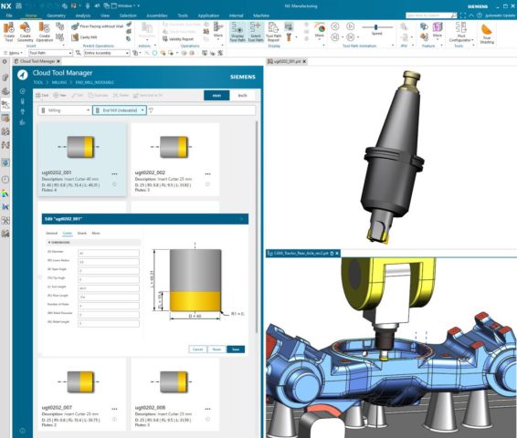
The Cloud Connect Tool Manager is a graphic-based interface that makes it easy for you to manage tools and components for efficient tool data maintenance in NX CAM software. Users can also import tools from vendor databases using web technology.
The easy-to-use interface and graphical design simplifies the programming workflow for defining and editing tools, requiring fewer clicks than before. Users can swiftly find the exact tools they need, saving valuable time and effort with dynamic tool preview and dimensions.
2. New Features in NX CAM
There are four display modes and two search modes for easy navigation and viewing. The intelligent search function goes beyond basic queries and can recognize multi-formulas, symbols, and keywords. Import tools directly from vendor databases and gain access to an extensive library to optimize productivity and efficiency.

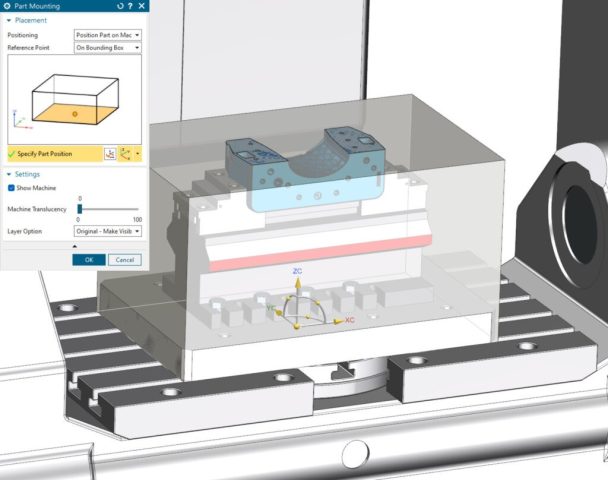
2.1 Position Part & Fixtures in Machine Context
The new enhancements to the Position Part & Fixtures in Machine Context allow users to quickly and accurately position CAM setup on the machine with improved usability and visibility. For example, users have dynamic handle positioning with a bounding box or cylinder and can position part and associated fixture assemblies. Move setups dynamically instead of the machine and gain better visibility of setup in the machine tool.
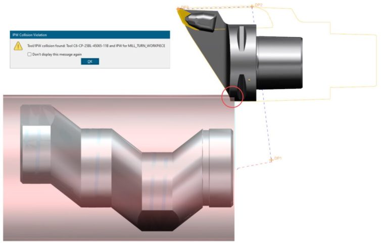
2.2 Automatic Turning Tool Holder Collision Shape Creation
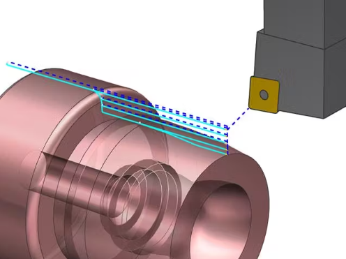
The new feature for Automatic Turning Tool Holder Collision Shape Creation provides increased process safety for holder collision checks. Users no longer need to manually specify collision shape and layer settings during the tool creation process, eliminating possible programming errors. The 2D holder shape geometry for turning tool holder is now created automatically during tool path verification.
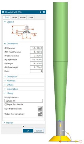
2.3 Dovetail Mill
The Dovetail Mill Tool enhancement simplifies tool creation using industry naming terminology, allowing you to easily specify basic Dovetail tool parameters. Dovetail Tools supports the following operation types including Planar Mill, ZLevel Undercut, Solid Profile and 3 Axis Deburring.
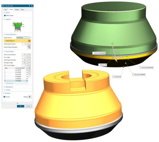
2.4 Simplified Shank Creation
The Simplified Shank Creation is now available to easily define shank data while achieving more accurate representation of shanks. Reduce the risk of redundancies by organizing data in a multi-shank library so shank management is simplified. Define multiple step shanks by extracting shank data from 3D parts in the same way that holders are currently defined, making complex multiple step shank definitions much easier.
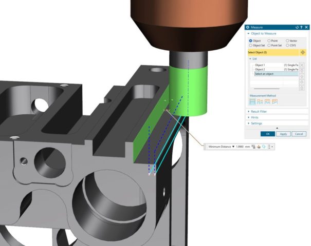
2.5 Distance Measure with Pick on Path
The Distance Measure with Pick on Path provides a quick way of verifying tool path related measurements. When the tool path is displayed, users can easily measure the distance between two points on a toolpath or between a point on the toolpath and a geometric object. It also facilitates the easy validation of measurements between a point on the toolpath and the cutting tool, as well as between the cutting tool and a geometric object.
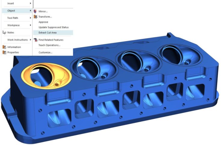
2.6 Extract Operation Cut
The Extract Operation Cut Area enables easier reuse of selected geometry for other operations. Users can now extract Cut Area selection from an operation reuse as a “Mill_Area” for subsequent operations.
(Source: Siemens)
For more information, please contact:
Vietbay CAD/CAM/CAE/PLM Team
Phone/Viber/Zalo/Whatsapp: 091 929 5520
Email: [email protected]
Website: www.vietbay.com.vn * www.cadcamcae.vn * www.vietbay.edu.vn