The latest version, NX 2412, has been released. The December 2024 NX release has been enhanced with many new and exciting features to help boost your productivity. In this post, we will dive into the new benefits and functions in design — focusing on Core Design, Design in Context, and Advanced Shape Design.
Core Design
Sketch
Building upon the Sketch Navigator management changes introduced in the previous NX 2406 version, continuous management of geometry, geometric relationships, and dimensions is now provided. Sketch Navigator is divided into tabs (Curves, Relations (Found and Persistent), External References, and Issues) and columns with functions such as Title, Status, Source, and Value to streamline your workflow. A new Sketch Checking feature in NX 2412 alerts users to potential issues in sketches, displaying results in Sketch Navigator and as visual tags in the graphics window:
- Right-clicking on the Tags allows users to auto-fix, ignore, or disable the check.
- A dialog box controls what is checked and tolerance checks.
- Enable tag display and populate Sketch Navigator by turning on the Sketch Checking icon on the Ribbon bar.
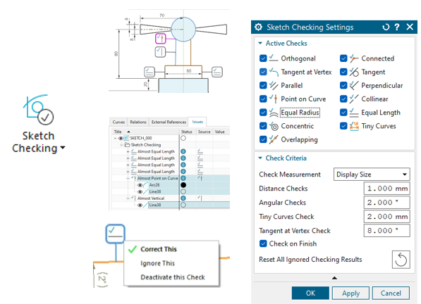 Detect potential issues in your 2D sketches with Sketch Checking.
The Found Relation for Slots feature is a newly added functionality to improve working with slot objects in the design environment. The system can automatically find and display relationships related to slot objects, such as dimensions, positions, or associated geometric constraints.
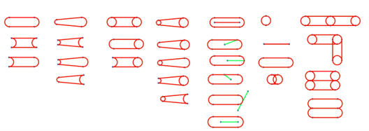 Supported slot shapes
Faster assembly load times for JT files with symbolic threads
NX load options now support Minimal Load for JT files with Thread features:
- Thread details are only loaded when a component is set as the Work Part.
- Threads are created for specific components rather than all components.
- Separates thread loading from the customer default of “Always Load PMI.”
- Aligns with the initiative to always load in Minimal Load and maintain minimal loading until fully required.
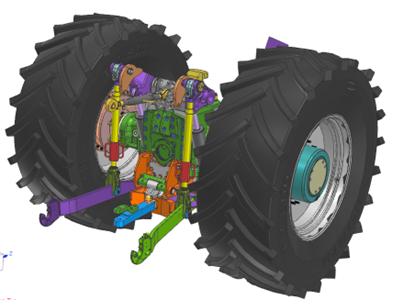 Support for loading components with symbolic threads when working with JT files.
Standard thread table validated
The metric thread *.xml table has been updated to current standards to provide accurate information about thread specifications. Validated thread details include major diameter, minor diameter, pitch diameter, standard, size, and pitch according to ISO-261 for both Metric Course and Metric Fine standards. Specific updates have been made for GJB3.4 and GB5796 to match DIN-ISO-5855-1 standards.
Additionally, the display of symbolic threads as decals has been improved for more intuitive design representation.
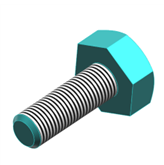 Symbolic threads displayed as decals
Flexible feature reference remapping in Paste Feature
Paste Feature now provides options to Reselect or Redefine feature inputs. The Reference Behavior option offers two choices to remap feature inputs. Reselect allows remapping to identical inputs. Redefine offers greater flexibility by allowing remapping to new object types (including indirect references). Paste Feature allows remapping feature inputs, including rule-based selections.
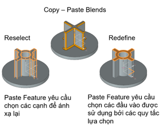 Flexibility in Paste Feature
Design in Context
Significantly improved performance when importing DXF/DWG files with Display Instances
When importing DXF/DWG files, using the Display Instances option creates lightweight representations for drawing block layouts. Display Instances are visual substitutes for actual geometry, intended to provide visual guidance or measurements. Display Instances are shown in Part Navigator. This is particularly beneficial for workflows in the Line Designer environment (90% faster NX save times! 75% file size reduction!).
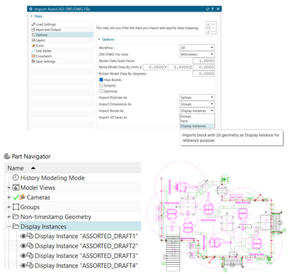 Boost performance when importing DWG/DXF files.
Display part relationships within the assembly structure context
Diagramming tools are ideal for top-down design and help visualize and validate best modeling practices across parts.
Filters allow analysis of specific types of part relationships (e.g., cyclic, upward, horizontal, etc.). Displays WAVE relationships outside of assemblies. Open and edit WAVE links from parts.
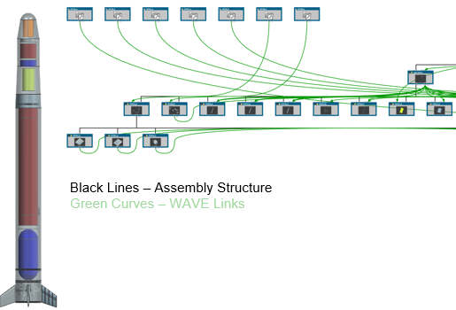 Visualize part relationships within the assembly context.
Advanced Shape Design
Build and refine complex wireframe shapes on surfaces
Continuing from previous improvements to Curve on Surface, the new Blend Curve on Surface command allows users to add more detail to curve-based modeling processes (fillet or chamfer). Curves must lie on the same surface. Additionally, new options to Delete and Replace input curves are available when creating Composite Curves without linking (using Join Curves).
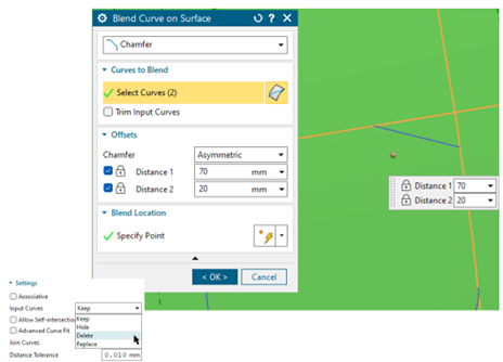 Edit curves on surfaces.
High-quality output for lofted surfaces
The Split Output along Boundary Curves option is now available in Through Curves, Ruled Surface, and Studio Surface results, improving internal surface continuity.
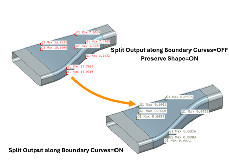 Improve lofted surface quality.
Output will be divided into multiple surfaces along sectional input segments and internal curves. Continuity between surfaces is maintained. For Studio Surface, internal continuity improvements are only available for loft-type surfaces. Point-based alignment is improved to maintain consistency with any point type.
Read more:
- Integrated Data Management With NX X
- Automating Wire EDM Programming with NX CAM Advanced Wire EDM (OptiCAM)
- What’s new in NX: Core Design
Contact us for free and detailed advice:

