
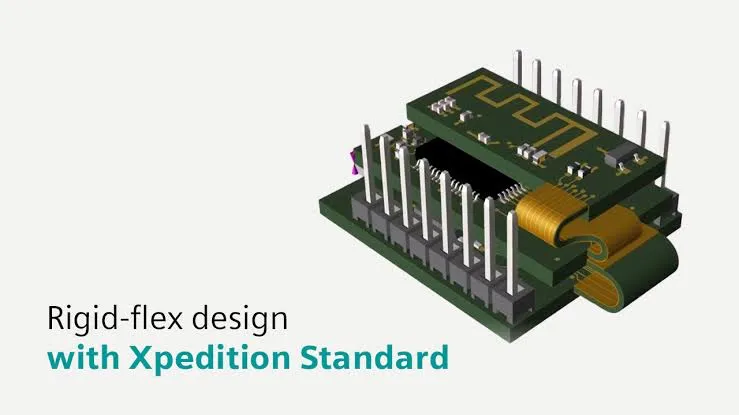
As electronic products become increasingly compact, flexible, and space-efficient, rigid-flex PCBs are becoming a practical choice for a wide range of applications, from compact medical devices to next-generation automotive and aerospace systems.
However, rigid-flex PCB design introduces specific requirements related to structural configuration, materials, bend radius, and coordination between mechanical and electronic design. Choosing the right design tools is therefore just as important as having the necessary engineering expertise.
Xpedition Standard provides scalable, intuitive design capabilities that help engineering teams address the specific requirements of rigid-flex PCBs, from layer stack-up configuration to design verification and MCAD-ECAD data synchronization.
1. Why Is Rigid-Flex PCB Technology Increasingly Popular?
Compact size, low weight, and durability are key advantages driving the adoption of rigid-flex PCBs in modern electronic devices.
Rigid-flex PCBs combine the reliability and high component density of rigid PCBs with the mechanical flexibility of flexible circuits. This allows boards to bend, twist, and fit into confined spaces.
This structure can also reduce dependence on connectors, minimizing connection points that could otherwise affect system reliability.
However, rigid-flex design involves more technical considerations than conventional PCB design, including:
- Controlling the bend radius
- Establishing an appropriate layer stack-up
- Selecting and managing specialized materials
- Ensuring compliance with manufacturing requirements
- Synchronizing data between mechanical and electronic design environments
Xpedition Standard addresses these challenges through an integrated design workflow, helping reduce complex manual operations and improve the likelihood of achieving an accurate design from the outset.
2. See How Xpedition Standard Supports Rigid-Flex PCB Design
The overview video below demonstrates how Xpedition Standard supports engineering teams throughout the rigid-flex PCB design process, from layer stack-up management to design verification and data coordination.
Key capabilities include:
- Intuitive Stack-up Editor: Define and manage rigid and flex regions within the PCB layer stack-up.
- Real-time design verification: Automatically check requirements such as bend radius, design constraints, and design for manufacturability (DFM).
- Support for teams of different sizes: Maintain data continuity and facilitate collaboration throughout product development.
- MCAD-ECAD integration: Synchronize mechanical and electronic design data through a co-design workflow, reducing discrepancies and shortening development cycles.
3. Key Xpedition Standard Features for Rigid-Flex Design
3.1. Integrated, Scalable Rigid-Flex Design Workflow
Rigid-flex design capabilities can be activated through a token-based licensing mechanism when needed. These capabilities are integrated into the Xpedition Standard design workflow, helping users maintain data continuity throughout product development.
As a result, design teams can reduce the need to switch between multiple tools, convert data between systems, or repeatedly develop new training workflows when expanding their design capabilities.
3.2. Intuitive Definition of Layer Stack-up Regions
The Stack-up Editor enables users to visualize and configure rigid and flex regions within the PCB stack-up.
Parameters such as copper weight, dielectric layers, adhesive layers, and coverlay can be configured directly in the design environment, giving engineers greater control over PCB structure and accuracy.
3.3. Automated Design Rule Checking
Xpedition Standard supports Dynamic Design Rule Checking (DRC), continuously checking important design parameters throughout the design process. These checks can cover:
- Bend radius
- Trace width and spacing
- Component placement
- Manufacturing-related requirements
Identifying potential issues during design allows engineers to address errors before manufacturing. This helps reduce the risk of problems that could otherwise require costly modifications in later project stages.
3.4. MCAD Co-Design
Rigid-flex PCB design often requires close collaboration between mechanical and electrical engineering teams. Xpedition Standard supports bidirectional data exchange with mechanical CAD software, helping synchronize designs across both environments.
The MCAD-ECAD co-design workflow enables teams to review and validate designs together, reducing discrepancies that might otherwise emerge late in a project.
When integrated with Siemens NX, users can also synchronize layer properties, design variants, and other relevant data.
3.5. Real-Time Collaboration
Xpedition Standard supports sharing layer stack-up configurations, design data, and mechanical outlines with stakeholders and manufacturing partners through a cloud-based platform.
This capability facilitates iterative design, allowing multiple parties to participate in design validation and refinement. As a result, teams can improve coordination and help shorten product development cycles.
Read more:
- TOP 5 Advantages of Xpedition Standard for PCB Design
- Introduction to Xpedition and Siemens Licensing Editions
- Xpedition Standard: A Solution to Shorten PCB Design Cycles by Up to 50%
4. Tăng tốc quy trình thiết kế Rigid-Flex
Xpedition Standard provides rigid-flex design capabilities for teams of different sizes, from individual engineers to expanding product development teams.
By automating and integrating key stages of the design process, Xpedition helps businesses:
- Shorten design and product development cycles
- Reduce design iterations and prototype rebuilds (design spins)
- Improve first-pass design quality
- Lower development and manufacturing costs
These capabilities help businesses accelerate the development of electronic products with demanding requirements for size, flexibility, and integration while optimizing the resources allocated to design.
Contact Vietbay – Siemens’authorized software distribution partner in Vietnam, for a consultation on rigid-flex PCB design solutions.