
How would you like your burger done? Medium rare, well done, or 3D printed? Seems farfetched? Well, not so much, if the recent 3D printing trends are anything to go by. All said and done, while I am a fan of this new, potentially revolutionizing technology, I think I will stick to having my burger made the good old-fashioned way.In today’s industries, designs are usually based on the manufacturing methods prevalent, but we have seen designs intended to only be manufactured by 3D printers instead of the traditional approaches. Therefore, we can claim that a designer’s creation depends heavily on the manufacturing methods. 3D printing offers much greater flexibility in terms of manufacturability, compared to the traditional methods. However, it begs the question: are our design tools and methods in a position to take full advantage of this manufacturing flexibility? While design trends are definitely headed that way, design tools and methods must evolve quickly to support these trends in order to take full advantage of the 3D printing manufacturing capabilities. And that is where Altair OptiStruct comes in.
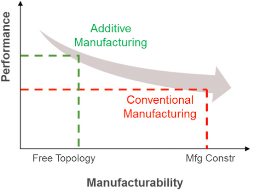
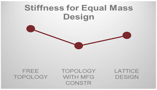
Now, in order to obtain meaningful results from a topology optimization, the implementation was modified to suit the current conventional manufacturing techniques such as casting, extrusion, stamping, etc. Let’s take a look at the impact this approach has had on the performance of the design:
Topology optimization and 3D printing bear many similarities in their philosophies:
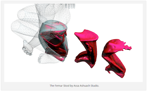
- 3D printing allows freedom of form. Complex designs can be easily manufactured, and designs are customized. It facilitates accelerated production since there is no need to develop for tooling.
- On the design side of the spectrum, topology optimization takes full advantage of the package space provided. It finds freeform and efficient material layouts where unique designs can be created, and the overall design process is shortened because design iterations are minimized.
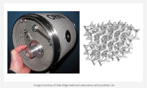
Now, let’s take a closer look at a design characteristic that can only be built using 3D printing techniques – lattice structures. Lattice structures involve repetitive patterns of a particular cell shape or type. There are libraries of cell types, and the density of these cells in a design is based on the application and loading that the design experiences. A couple examples of lattice structures are displayed below.
Apart from being unique to 3D printing, lattice structures bear some desirable characteristics from a design perspective. For example, due to the large network of structural members, the design exhibits better performance for stability. The large network of members also results in larger surface area, making these designs desirable for thermal behavior, such as for heat sinks. They also have desirable weight characteristics, and are used as an approach to target weight reduction. Additionally, lattice designs are great for biomedical applications, such as implants, as the porous nature of the structure facilitates bone and tissue growth and attachment.In the latest release of OptiStruct, we implemented the functionality to generate lattice structures. What is unique about this is that we don’t simply fill a volume with a lattice structure to reduce weight, but instead, we use optimization – topology optimization – to drive the material layout including the lattice regions. From this new topology optimization implementation in OptiStruct, we are able to identify void regions in the design space, where the material can be removed, regions where solid material is needed, and regions where lattice structure is required. This allows us to generate the optimal hybrid or blended solid-lattice design based on desired functionality of the part.
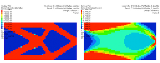
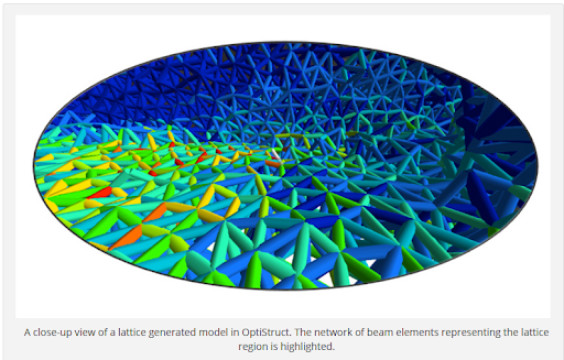
Lattice structures can be considered as porous structures. In the case of topology optimization, the semi-dense elements are like the porous media. With the traditional topology optimization formulation, these semi-dense elements have been penalized to produce more discrete structures like elements with either 0 or 1 as density, where 0 indicates voids and 1 indicates the existence of material. Now that 3D printing enables us to manufacture these “porous” structures, which are essentially lattice regions, we can allow the topology optimization to retain more “porosity” in the design space. In other words, the semi-dense elements are not penalized as much because we have methods to manufacture these semi-dense regions. A density range is used to identify lattice regions in order to interpret the design. Regions below the lower bound of the range are considered voids, while those above the upper bound threshold are considered solid. To aid in the overall process workflow and simplify the design engineers’ tasks, this interpretation is done automatically by OptiStruct, resulting in the generation of a complete finite element model representing the lattice structure design. The lattice regions of the model are interpreted as a network of beam elements describing a particular cell type.
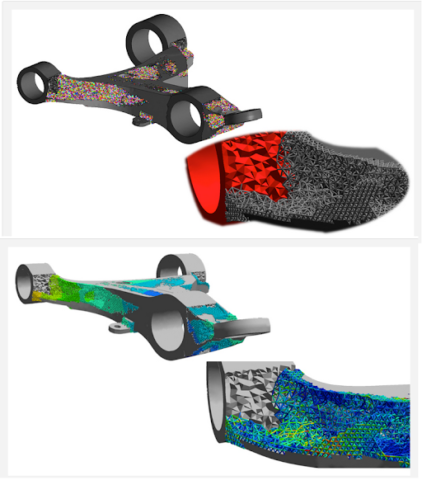
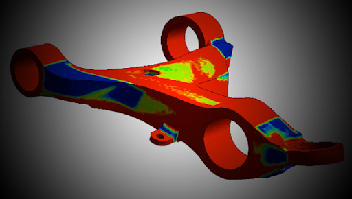
The following examples showcase the application of this process to optimize an automotive control arm designed for 3D printing by utilizing lattice structures.